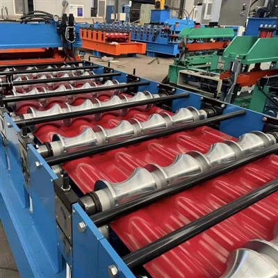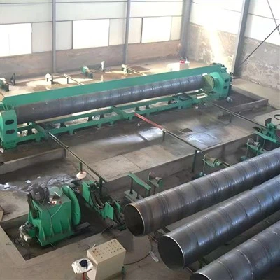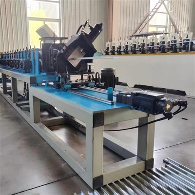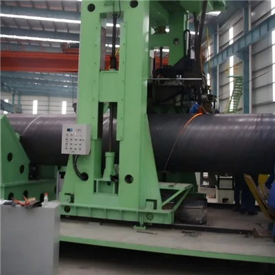
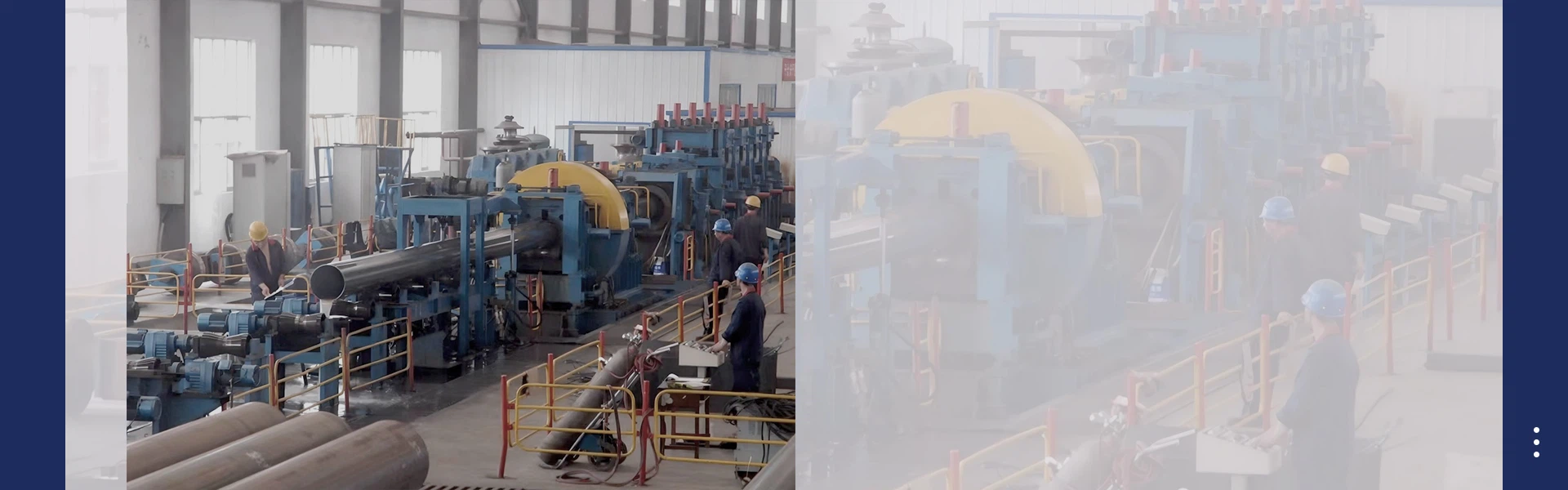
A Cable Tray Forming Machine is a specialized roll forming system used to manufacture metal cable trays for organizing and supporting electrical cables. Cable trays are widely used in factories, warehouses, commercial buildings, power plants, infrastructure projects, and other electrical installations.
The machine continuously converts metal coils into accurately formed cable tray sections through a series of forming rollers. Depending on the product design, the production line can also integrate leveling, punching, cutting, automatic length measurement, and PLC control.
Unlike roofing-sheet roll forming equipment, a cable tray machine must be designed around the structural requirements of the tray. Tray width, side-wall height, flange configuration, hole pattern, material thickness, and load requirements all influence the machine design.

What a Cable Tray Does
A cable tray provides a dedicated route for electrical, control, communication, and instrumentation cables. It keeps cables organized while supporting them along horizontal or vertical installation routes.
Depending on the project, cable trays can be manufactured in different designs, including perforated trays, solid-bottom trays, channel trays, and ladder-type systems.
The required design depends on factors such as cable quantity, ventilation requirements, installation environment, mechanical loading, and project specifications.
How a Cable Tray Forming Machine Works
The production process begins with a steel coil loaded onto the decoiler. The coil is gradually unwound and fed into a leveling and guiding system.
If the finished tray requires holes or slots, a punching system creates the required pattern. The strip then enters the roll forming section, where a series of rollers progressively bends it into the required tray shape.
After forming, the continuous profile is cut into predetermined lengths.
The general production sequence is
Decoiling → Leveling → Guiding → Punching → Roll Forming → Cutting → Finished Cable Tray
The exact sequence can change depending on the tray design and machine configuration.
Main Components of the Production Line
A typical Cable Tray Production Line can include several integrated units.
|
Component |
Main Function |
|
Decoiler |
Unwinds the steel coil |
|
Leveling unit |
Removes coil curvature |
|
Feeding system |
Controls material entry |
|
Punching unit |
Creates holes and slots |
|
Roll forming unit |
Produces the tray profile |
|
Cutting unit |
Cuts the continuous tray |
|
PLC system |
Controls the production process |
|
HMI |
Allows parameter input |
|
Run-out table |
Supports finished products |
For larger production facilities, automatic stacking and packing systems can also be added.
Different Cable Tray Designs
The profile is one of the most important considerations when designing the machine.
A simple channel tray consists of a base with raised side walls. A perforated tray contains regularly arranged openings, while a solid-bottom tray has a continuous metal base.
Ladder cable trays have two longitudinal side rails connected by cross members and therefore require a different manufacturing and assembly arrangement.
A machine should always be designed according to the actual profile drawing rather than simply specifying "cable tray."
Perforated Cable Tray
Perforated cable trays contain openings in the bottom, side walls, or both. These openings can provide ventilation and reduce the overall weight of the tray.
The hole arrangement can be customized according to the required product.
Important punching parameters include
- Hole diameter
- Hole width
- Hole length
- Hole spacing
- Hole pitch
- Number of rows
- Distance between holes
- Hole position
The punching equipment must be accurately synchronized with the material-feeding system.
Solid-Bottom Cable Tray
Solid-bottom cable trays have a continuous base without regularly distributed holes. They can be used when greater cable support or additional protection from dust and falling particles is required.
Since the product does not require a perforation pattern, the production process can be simpler than that of a perforated tray.
However, the forming section still needs to maintain accurate side-wall dimensions, straightness, and profile geometry.
Ladder Cable Tray
Ladder cable trays consist mainly of two side rails connected by regularly spaced rungs. This structure provides open access to cables and allows substantial ventilation.
The manufacturing process can differ from continuous sheet-metal tray production because the side rails and cross members may be manufactured separately and then assembled.
For larger-scale production, dedicated punching, forming, cutting, and automatic assembly equipment can be incorporated into the production system.
Cable Tray Dimensions
Cable trays are manufactured in many different widths and heights according to installation requirements.
Common tray widths can include approximately
50, 100, 150, 200, 300, 400, 450, 500, 600, 750, and 900 mm
Side-wall heights may commonly range from approximately
50 to 200 mm
These are only examples. The actual dimensions depend on the manufacturer's product range and the requirements of the relevant project or standard.
A machine can be designed for one fixed size or for multiple adjustable sizes.
Material Thickness
Material thickness has a direct effect on the machine's forming capacity.
Many cable tray applications use steel in approximately the 0.8–2.5 mm range, while heavy-duty applications can require thicker material.
The appropriate thickness depends on
- Tray width
- Side-wall height
- Support spacing
- Cable load
- Steel grade
- Tray geometry
- Project requirements
Thicker material generally requires greater forming force and stronger machine components.
Materials Used for Cable Trays
Galvanized steel is widely used for cable tray production because its zinc coating provides corrosion protection.
Other materials can also be used depending on the installation environment and product requirements.
Common options include
- Galvanized steel
- Pre-galvanized steel
- Stainless steel
- Aluminum
- Other coated steel
Stainless steel can be suitable for more corrosive environments, while aluminum can provide a lightweight alternative.
The forming machine must be designed according to the mechanical properties of the selected material.
Coil Width and Developed Width
Coil width is determined by the developed width of the finished cable tray profile.
The flat strip must contain enough material to form the bottom, side walls, flanges, and other profile features.
For example, a tray with a 300 mm base and 100 mm side walls requires substantially more flat material than a simple 300 mm-wide flat sheet.
Therefore, the coil width cannot be selected based only on the finished tray's overall width. The complete profile must be developed and calculated before the roll tooling is designed.
Side-Wall Height
Side-wall height is an important variable in both the machine design and the final structural performance of the tray.
A deeper side wall can provide greater structural rigidity and increase the cable containment capacity. However, it also increases the developed strip width and can require additional forming stages.
The rollers must progressively form the side walls without causing excessive springback, deformation, cracking, or coating damage.
Flange Configuration
Some cable trays have flanges along the upper edges of their side walls.
These flanges can improve rigidity and may provide a suitable connection surface for covers or accessories.
The flange shape and dimensions must be included in the profile drawing because even relatively small changes can affect the forming sequence and roller design.
Punching System
Punching is an essential part of many cable tray production lines.
Perforated trays require accurate holes or slots at predetermined locations. Depending on the design, the punching process can take place before roll forming or at another stage of production.
Hydraulic punching systems are commonly used for heavier materials, while servo-controlled punching systems can provide flexible positioning and high repeatability.
The correct punching system depends on
- Material thickness
- Hole dimensions
- Number of holes
- Production speed
- Positioning accuracy
- Tray profile
Punching Accuracy
Accurate punching is important because cable trays are often connected using bolts, brackets, clamps, couplers, and other accessories.
Incorrect hole positioning can make installation difficult and may cause alignment problems between tray sections.
An encoder measures material movement, while the PLC uses this information to trigger the punching system at the programmed position.
For manufacturers producing different hole patterns, the control system can store multiple production programs.
Roll Forming Process
After feeding and punching, the steel strip enters the roll forming section.
The forming rollers progressively bend the flat strip into the required cross-sectional shape. Instead of forming the entire profile in one operation, each roller station performs a controlled amount of deformation.
A simplified forming sequence can be
Flat Strip → Edge Bending → Side-Wall Formation → Flange Formation → Final Calibration
The actual sequence depends on the profile geometry.
Number of Forming Stations
A cable tray machine may use approximately 10–20 or more forming stations, depending on the complexity of the profile.
A simple channel profile may require fewer stations, while a tray with high side walls, multiple flanges, or special edge geometry may require additional stations.
The number of stations alone does not determine machine performance. Roller design, shaft diameter, station arrangement, alignment, and forming calculations are equally important.
Production Speed
Production speed depends on several factors, including material thickness, tray dimensions, punching requirements, profile complexity, and machine configuration.
Many cable tray roll forming machines operate at approximately 8–20 m/min, while specialized systems can be designed for higher speeds.
However, the maximum machine speed and actual production speed should not be treated as the same figure.
A complex perforation pattern can reduce practical output because the punching process may become the limiting factor.
Cutting System
After the profile has been formed, the continuous cable tray is cut into individual sections.
Common finished lengths include
- 2 m
- 2.4 m
- 3 m
- 4 m
- 5 m
- 6 m
Customized lengths can also be produced through PLC-controlled length settings.
The cutting system can be hydraulic or servo controlled depending on material thickness, production speed, and required accuracy.
Flying Cutting and Stop Cutting
Two common cutting approaches are stop cutting and flying cutting.
With stop cutting, the material stops when the programmed length is reached, and the cutter then operates.
With flying cutting, the cutting unit can operate while the material continues moving. This can increase production efficiency, particularly at higher speeds.
Flying cutting requires accurate synchronization between the encoder, PLC, feeding system, and cutting mechanism.
PLC and HMI Control
Modern Cable Tray Roll Forming Machines generally use PLC-based control systems.
The operator can enter parameters such as
- Product length
- Production quantity
- Punching pattern
- Hole position
- Production speed
- Cutting parameters
The HMI displays machine status, production quantity, alarms, and operating information.
For manufacturers producing several cable tray sizes, product programs can be stored for easier changeover.
Fixed and Adjustable Machines
Cable tray machines can be designed as fixed-profile or adjustable systems.
A fixed-profile machine is optimized for one specific tray size or a small group of closely related profiles. This configuration can be suitable for high-volume production of a standardized product.
An adjustable machine can produce multiple tray widths or heights within a defined mechanical range.
For example, an adjustable system might be designed for tray widths ranging from approximately 100 to 600 mm.
However, the actual adjustment range must be confirmed during machine design. An adjustable machine cannot produce unlimited profile combinations.
Cable Tray Cover Production
Cable tray covers are commonly manufactured separately because their cross-section differs from the tray itself.
A manufacturer supplying a complete cable management system may therefore use both a tray production machine and a dedicated cover roll forming machine.
The cover can be designed with different edge shapes, flanges, or locking arrangements depending on the tray system.
Quality Control During Production
Dimensional consistency is particularly important because cable trays must connect correctly with couplers, elbows, tees, reducers, brackets, and covers.
Important inspection points include
|
Parameter |
Inspection Focus |
|
Tray width |
Dimensional accuracy |
|
Side-wall height |
Profile consistency |
|
Flange |
Width and angle |
|
Hole diameter |
Punching accuracy |
|
Hole spacing |
Correct pitch |
|
Finished length |
Cutting accuracy |
|
Straightness |
Longitudinal deformation |
|
Surface |
Coating condition |
|
Material thickness |
Incoming coil verification |
Regular inspection can identify forming, punching, or cutting problems before a large quantity of defective products is produced.
Common Production Problems
Several problems can occur during cable tray manufacturing.
Profile Deformation can result from incorrect roller alignment, excessive forming force, or unsuitable forming parameters.
Hole Position Errors may occur when the encoder and punching system are not properly synchronized.
Surface Scratches can be caused by damaged forming rollers, contamination, or improper material guidance.
Uneven Side Walls can result from incorrect roller adjustment or variations in the incoming steel.
Springback can become more noticeable when high-strength steel is processed and may require appropriate tooling compensation.
Length Variation can result from encoder calibration problems, material slippage, or cutting-system synchronization.
Machine Maintenance
Regular maintenance is important for maintaining production accuracy.
Forming rollers should be inspected and cleaned regularly. Bearings and transmission components should be lubricated according to the equipment manufacturer's maintenance schedule.
Punches and dies require particular attention because wear can affect hole dimensions and positioning.
Hydraulic components should be checked for leakage and correct operating pressure. Electrical cabinets, sensors, encoders, PLC components, and safety devices should also be inspected periodically.
Keeping the production line clean helps reduce contamination and protects both machine components and finished products.
How to Select a Cable Tray Forming Machine
Before purchasing the machine, the manufacturer should clearly define the required product range.
Important specifications include
- Tray type
- Tray width
- Tray height
- Side-wall design
- Flange dimensions
- Material type
- Material thickness
- Coil width
- Hole pattern
- Hole dimensions
- Finished length
- Required production speed
- Production quantity
- Fixed or adjustable profile
- Automation requirements
A detailed profile drawing is strongly recommended. It allows the machine manufacturer to calculate the developed width and design the forming rolls correctly.
Summary
A Cable Tray Forming Machine is a specialized production system for manufacturing metal cable trays with consistent dimensions and repeatable quality. Depending on the machine configuration, it can combine decoiling, leveling, punching, roll forming, cutting, and PLC-controlled automation into one production line.
The equipment can be designed for different products, including perforated cable trays, solid-bottom trays, channel trays, and certain ladder-type cable tray components.
The most important machine variables include tray width, side-wall height, flange configuration, material type, material thickness, coil width, punching pattern, finished length, production speed, and adjustment range.
For many applications, material thickness may fall within approximately 0.8–2.5 mm, while practical production speeds can be around 8–20 m/min. These figures are indicative, and the actual machine capacity should always be determined by the specific tray profile and production requirements.
The most important step when ordering a machine is to provide the exact cable tray profile drawing and material specifications. This allows the forming rollers, punching system, cutting equipment, drive system, and control system to be properly matched to the intended product.
A properly designed cable tray production line can provide reliable dimensional accuracy, repeatable punching, efficient production, and the flexibility required to manufacture different cable management products for electrical and industrial applications.