
Spiral Pipe Machine Installation Instructions
A spiral pipe machine (also known as a spiral welding pipe machine or SSAW pipe machine) is the core heavy-duty industrial equipment for producing spiral seam welded steel pipes. It is widely used in key fields such as oil and gas transportation, municipal water supply and drainage, construction engineering, and energy infrastructure. Its installation quality directly determines the stability of equipment operation, production efficiency, precision of finished pipes, and service life. To standardize the installation process, avoid potential safety hazards, and ensure that the equipment meets the designed operating standards after installation, these installation instructions are specially formulated.
Pre-installation Preparation
Pre-installation preparation is the premise to ensure the efficient, safe and orderly progress of the installation work. It is necessary to complete three core preparation tasks: personnel, equipment and materials, and on-site preparation. All links must comply with industrial equipment installation specifications and the technical requirements of the equipment manufacturer.
1. Personnel Preparation
The installation of a spiral pipe machine involves multiple professional links such as hoisting, mechanical assembly, electrical wiring, and quality inspection. A professional construction team must be set up to clarify job responsibilities. All personnel must receive professional training and pass the assessment before taking up their posts; unlicensed operation is strictly prohibited.
2. Equipment and Materials Preparation
Before installation, it is necessary to check each equipment component one by one to ensure they are complete and intact. At the same time, prepare the tools and auxiliary materials required for installation to avoid work stoppages due to lack of materials during the installation process and ensure the installation progress is not affected.
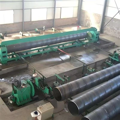
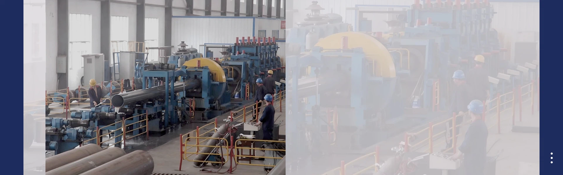
A spiral pipe machine is mainly composed of a feeding preprocessing unit, a spiral forming unit, a welding unit, an auxiliary unit, and a control system. The manufacturer will disassemble the equipment into multiple components when delivering the goods. On-site, it is necessary to check each component one by one against the "Equipment Component List". Core components include uncoiler, pinch leveler, shear butt welding machine, forming machine, internal welding device, external welding device, rear axle, flying cutting cart, edge milling machine, end facing and chamfering machine, PLC control cabinet, and main machine embedded parts. Focus on checking whether the model and specification of core components (such as forming rolls, welding torches, flying cutting carts, etc.) are consistent with the design, and whether there are any damages, deformations, rust or other defects. After the inspection is completed, fill in the "Component Inspection Record Form", which must be signed and confirmed by the inspector before entering the installation link.

Preparation of Installation Tools and Auxiliary Materials
Installation tools must be debugged in advance, and auxiliary materials must meet industrial installation standards and the requirements of the equipment manual. The specific list is shown in the following table to ensure that the tools are in good performance and the auxiliary materials are of matching specifications:
|
Category |
Specific Name |
Specification Requirements |
Core Purpose |
|
Hoisting Tools |
Truck Crane |
16t-50t (selected according to the weight of the equipment; 50t for large units) |
Hoisting the main equipment and large components (such as forming machine, rear axle) |
|
Manual Hoist |
2t-5t |
Hoisting small components and fine-tuning positions to accurately align installation interfaces |
|
|
Steel Wire Rope |
Diameter 12mm-20mm, tensile strength ≥1800MPa |
Binding hoisting components to ensure stable and safe hoisting process and avoid slipping |
|
|
Lifting Sling |
Matching the specifications of the equipment lifting points, with protective cushion |
Fixing hoisting components to protect the equipment surface paint and precision structure |
|
|
Assembly Tools |
Torque Wrench |
0-300N·m, accuracy ±1N·m |
Tightening bolts to ensure torque meets standards and prevent equipment vibration and loosening during operation |
|
Level Meter |
Accuracy 0.02mm/m |
Detecting the levelness and verticality of equipment installation to ensure installation accuracy |
|
|
Tape Measure |
5m-30m, accuracy ±1mm |
Measuring installation dimensions and component spacing, and verifying installation positions |
|
|
DC Welding Machine |
Current 0-500A, adjustable |
Welding and fixing components, and sealing and reinforcing anchor bolts |
|
|
Auxiliary Materials |
Anchor Bolt |
M24-M36, length determined according to foundation depth (≥100mm) |
Fixing the equipment base to ensure stable equipment operation and prevent settlement |
|
Lubricating Oil/Hydraulic Oil |
Industrial grade gear oil and hydraulic oil (meeting the requirements of the equipment manual) |
Lubricating equipment components to reduce wear and ensure smooth operation |
|
|
Sealant |
High temperature resistant, high pressure resistant, waterproof and oil proof |
Sealing equipment interfaces and pipeline connections to prevent oil and gas leakage |
3. On-site Preparation
The installation site must meet the requirements of equipment installation and safe operation, and be cleaned and planned in advance to create good conditions for the installation work. The specific preparation items are as follows:
- Site Cleaning: Remove debris and obstacles from the installation site, level the ground, ensure that the hoisting channel and operation space are unobstructed. The site area must be more than 1.5 times the area occupied by the equipment to avoid affecting hoisting and assembly operations.
- Foundation Layout: According to the "Equipment Foundation Drawing" provided by the manufacturer, mark the equipment installation reference line and foundation position line on the ground, and mark the position of the anchor bolt reserved holes. The layout accuracy error shall be ≤2mm. The foundation drawing shall be provided to the user in advance to facilitate the early foundation construction and reserve the anchor bolt installation holes and embedded part installation positions.
- Water and Electricity Preparation: Connect the temporary power supply at the construction site (380V, 50Hz, capacity meeting the needs of equipment commissioning and tool use), arrange temporary water supply pipelines to ensure sufficient construction water and equipment cooling water, and control the compressed air pressure at 0.5~0.8MPa.
- Safety Protection: Set up safety warning signs on the site (such as "Hoisting Operation, No Entry", "High Voltage Danger", "Construction Area, Pay Attention to Safety"), divide the operation area, set up protective railings, and equip sufficient fire-fighting equipment (fire extinguishers, fire sand) to ensure safe operation.
Equipment Foundation Construction
The spiral pipe machine is a heavy-duty equipment that will generate vibration during operation. The foundation construction must meet the bearing requirements to prevent settlement and displacement of the equipment during operation. The foundation construction must be carried out in strict accordance with the "Equipment Foundation Drawing" provided by the manufacturer and relevant specifications. The core steps are as follows:
1. Foundation Excavation
According to the foundation layout position, use an excavator for foundation excavation. The excavation depth and width must meet the design requirements: the foundation depth of large spiral pipe machines is generally 1.2m-1.8m, and the foundation depth of small equipment is 0.8m-1.2m. The foundation pit width is 300mm-500mm wider than the design width of the foundation to facilitate formwork installation and concrete pouring. During the excavation process, timely clean up the floating soil and debris in the foundation pit to ensure that the foundation pit is level. The bottom of the foundation pit must be compacted with a compaction density ≥95% to prevent later settlement.
2. Steel Bar Binding and Formwork Installation
Bind the steel bars according to the foundation design drawings. The specification, spacing and quantity of the steel bars must meet the requirements. The steel bar joints are connected by welding, and the welding quality must meet the standards to avoid false welding and missing welding. After binding, install the steel formwork. The formwork must be firmly installed with a verticality error ≤3mm/m. The gap between the formwork and the foundation pit wall must be sealed with cement mortar to prevent slurry leakage during concrete pouring and ensure the foundation forming quality.
3. Reserved Anchor Bolts and Embedded Parts, Concrete Pouring
Fix the anchor bolts in the formwork according to the design position to ensure that the anchor bolts are vertical and accurately positioned. The top of the bolts is 50mm-80mm higher than the foundation surface, and the bottom of the bolts is firmly fixed to prevent displacement during concrete pouring. As the ground reference of the entire spiral pipe machine unit, the installation accuracy of the embedded parts directly affects the accuracy of the entire unit. They must be installed synchronously with the anchor bolts to ensure accurate positioning and firm fixation. After the installation of the anchor bolts and embedded parts is completed, pour C30-C40 commercial concrete. During the pouring process, use a vibrator to vibrate to ensure that the concrete is dense without defects such as honeycombs, pitting surfaces, and cavities.
4. Foundation Maintenance
After the concrete pouring is completed, carry out foundation maintenance. The maintenance time shall not be less than 14 days. During the maintenance period, the surface of the concrete must be kept moist to avoid exposure to the sun and freezing. After the maintenance is completed, remove the formwork and check the flatness and verticality of the foundation surface. The flatness error of the foundation surface shall be ≤2mm/m, and the verticality error shall be ≤3mm/m. Unqualified parts must be repaired, and re-maintained after repair to ensure that the foundation strength meets the standards.
Main Equipment Installation

After the foundation maintenance meets the standards and the strength meets the requirements, start the main equipment installation. The installation sequence follows the principle of "from bottom to top, from core to auxiliary", and the base installation, forming unit installation, welding unit installation, auxiliary unit installation, and control system installation are carried out in turn to ensure that all components are connected smoothly and the installation accuracy meets the standards.
1. Base Installation
Use a truck crane to hoist the equipment base to the foundation, adjust the position of the base to align with the foundation layout reference line, use a level meter to detect the levelness of the base, and the levelness error shall be ≤0.5mm/m. After adjustment, pass the anchor bolts through the reserved holes of the base, tighten the nuts, and the torque value shall meet the requirements of the equipment manual (generally 150N·m-250N·m). Finally, seal the reserved holes of the anchor bolts with cement mortar to ensure that the base is firmly fixed without loosening.
2. Core Unit Installation
Spiral Forming Unit Installation
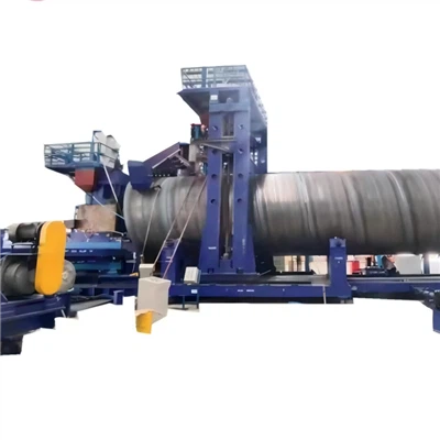
The spiral forming unit is the core of the spiral pipe machine, consisting of a base, vertical rolls, a pull beam device, 1~3# forming rolls and 4~8# external control rolls. It is responsible for bending the steel coil into a spiral pipe blank. Its installation accuracy directly affects the roundness of the finished pipe and the welding quality. Hoist the forming machine to the base, adjust the position of the forming machine to align with the center line of the base, and fasten the connecting bolts. Install the forming rolls and guiding devices, adjust the spacing and angle of the forming rolls to ensure that the forming rolls rotate flexibly without jamming, the forming angle meets the design requirements (generally 40°-83°), and the V-groove angle is adjusted to 60°-75° to ensure the subsequent welding quality.
Welding Unit Installation
The welding unit includes an internal welding device and an external welding device. The internal welding device is composed of a curved plate, an adjusting plate and an adjusting mechanism, which is used to fix and adjust the position of the internal welding torch. The external welding device is composed of a column, a crossbeam, a moving slide plate, etc., which is used to adjust and fix the position of the external welding torch. The mainstream welding method is single-wire internal welding and double-wire external submerged arc automatic welding. Hoist the welding frame to the designated position and fix it firmly. Install the internal and external welding torches, adjust the position of the welding torches to align with the spiral groove of the forming machine, ensure that the welding torches move smoothly and the angle is adjustable. Connect the welding power supply, wire feeding mechanism and flux recovery device, check that the lines and pipelines are firmly connected without loosening or leakage, and the welding power supply parameters are preset in place (DC-1500 type for internal welding, DC-1500 type and AC-1200 type for external welding).
Auxiliary Unit Installation
The auxiliary units include feeding preprocessing unit, shear butt welding unit, flying cutting cart, edge milling machine, end facing and chamfering machine, rear axle, etc. The installation sequence is as follows to ensure that each unit is connected smoothly with the main equipment:
- Feeding Preprocessing Unit: Install the uncoiler and pinch leveler, adjust the position of the uncoiler to ensure that the steel coil rotates flexibly after installation, which can adapt to steel coils with an outer diameter of Φ1200~Φ1800mm. Adjust the rolls of the leveler to be horizontal, and the leveling accuracy meets the requirements. The vertical rolls can be adjusted according to the change of plate width, and the pressing amount of the leveling rolls can be manually adjusted according to the change of plate thickness (4~20mm).
- Shear Butt Welding Unit: Install the shear machine and butt welding machine, adjust the shear blade gap of the shear machine (adjust according to the plate thickness) to ensure smooth shearing, align the electrode position of the butt welding machine, preset the welding parameters in place, and realize seamless connection of steel coils to ensure continuous production.
- Flying Cutting Cart: Composed of a base, a pneumatic system, a car body, a top wheel and a roller, it is used to cut steel pipes according to the fixed length (8~12m). Install the flying cutting cart on the output bracket of the rear axle, adjust the position of the cart to ensure that it is aligned with the steel pipe conveying direction, moves smoothly, and the cutting accuracy meets the standard (error ≤±5mm).
- Edge Milling Machine and End Facing and Chamfering Machine: The edge milling machine is used to mill the steel strip groove, which is composed of a milling cutter head, a frame, an adjusting device, etc. The end facing and chamfering machine is used to cut the end faces of steel pipes, which is composed of a base, a headstock, a cutter head, etc. Install the two machines to the designated positions, adjust their spacing from the main equipment to ensure smooth feeding and discharging, and the tools are firmly installed and adjusted in place.
- Rear Axle Installation: The rear axle is composed of an axle body, an output bracket, an output roller, etc., which can swing ±1° under the action of an oil cylinder to eliminate the misalignment and overlapping of steel pipe forming. Hoist the rear axle to the designated position, connect it firmly with the forming machine, and adjust the position of the output bracket and roller to ensure that it is consistent with the steel pipe conveying direction.
Control System Installation
Hoist the PLC control cabinet and operation panel to the designated position and fix them firmly. Connect the electrical lines and signal lines between the control cabinet and each equipment. The lines are arranged standardized, bundled neatly, and marked with line labels to prevent wrong connection. Install operation buttons and indicator lights to ensure convenient operation and clear display. Connect the control system with the hydraulic system and pneumatic system, debug the signal transmission, ensure that the control system can normally control the operation of the equipment, and can realize the precise adjustment of parameters such as welding speed (0.8~2.2m/min) and feeding speed (0.6~2.5m/min).
System Commissioning
After the equipment installation is completed, carry out system commissioning. The commissioning is divided into three stages: single-machine commissioning, linkage commissioning and load commissioning. During the commissioning process, make detailed records, timely troubleshoot faults, and ensure that all performance indicators of the equipment meet the standards and production requirements. The commissioning work must be completed by professional technicians; non-professional personnel are strictly prohibited from operating.
1. Single-machine Commissioning
Start each single-machine equipment one by one for no-load operation, and check the equipment operation status. The specific commissioning content and qualified standards are shown in the following table:
|
Equipment Name |
Commissioning Content |
Qualified Standards |
|
Uncoiler |
No-load rotation, tension adjustment, steel coil positioning |
Smooth rotation, no abnormal noise, flexible tension adjustment, no slipping, accurate steel coil positioning |
|
Forming Machine |
Forming roll rotation, angle adjustment, guiding accuracy |
Smooth rotation, no jamming, accurate angle adjustment, meeting design requirements, stable guiding |
|
Welding Equipment |
Welding power supply start-up, wire feeding, flux conveying, welding angle adjustment |
Stable operation of power supply, uniform wire feeding, smooth flux conveying, no leakage, flexible angle adjustment |
|
Flying Cutting Cart |
Movement, cutting action, fixed length accuracy |
Smooth movement, cutting accuracy ±5mm, no jamming or abnormal noise, accurate fixed length |
|
Control System |
Signal transmission, button operation, parameter adjustment |
Stable signal transmission, sensitive button operation, normal display of indicator lights, accurate parameter adjustment |
2. Linkage Commissioning
After the single-machine commissioning is qualified, carry out linkage commissioning. Start all equipment to simulate the production process and check the coordinated operation status between each equipment: the processes of feeding, leveling, forming, welding, cutting, etc. are connected smoothly without jamming or disconnection. The control system can accurately control the operation speed and parameters of each equipment, and the signal feedback is timely. The hydraulic system and pneumatic system have stable pressure without leakage. The flying cutting cart matches the steel pipe conveying speed, and the cutting length is accurate. The rear axle swings flexibly, which can effectively eliminate the forming misalignment and overlapping. During the commissioning process, if there are problems such as equipment jamming and parameter deviation, stop the machine in time for adjustment until the linkage operation is smooth.
3. Load Commissioning
After the linkage commissioning is qualified, carry out load commissioning. Use qualified steel coils (material Q235~X70, plate thickness 4~20mm) for trial production. The number of trial production shall not be less than 3-5 pieces. Check the dimensional accuracy and welding quality of the finished pipes: the outer diameter error of the steel pipe is ≤±0.2mm, the wall thickness error is ≤±0.1mm, and the spiral weld is flat without slag inclusion, pores, incomplete penetration and other defects, meeting the API spec 5L and SY/T5037-92 standards. During the equipment operation, the vibration and noise meet the standards (noise ≤85dB), and the temperature of each component is normal (motor temperature ≤75℃, bearing temperature ≤80℃).
Installation Safety Specifications
The installation process of the spiral pipe machine involves high-risk links such as heavy hoisting, high-altitude operations, and electrical operations. It is necessary to strictly abide by the safe operation specifications to eliminate safety accidents. The specific requirements are as follows:
- During hoisting operations, the hoisting tools must be inspected and qualified, and the hoisting plan must be confirmed by the installation commander. Unauthorized personnel are prohibited from entering the hoisting area. Operate stably during hoisting to avoid collision and slipping of components, and overloading hoisting is strictly prohibited. The steel wire rope must be firmly bound, and wood chips or rags must be clamped at the contact with the machinery to protect the equipment surface. Try to use the lifting lugs on the equipment for hoisting.
- During electrical operations, the temporary power supply must be cut off, and the sign "No Switching On, Work in Progress" must be hung. Live operation is strictly prohibited. The line connection must be standardized, and the grounding and zero connection protection must be in place to prevent electric shock accidents. Electrical equipment must be kept away from water sources and flammable materials to avoid short circuits and fires.
- During high-altitude operations (height ≥2m), operators must wear safety belts and safety helmets, set up safe scaffolding, and are strictly prohibited from throwing objects at high altitudes. Tools and materials must be placed firmly to prevent falling.
- During the equipment installation process, it is strictly prohibited to arbitrarily change the equipment structure and installation position. If adjustment is needed, it must be confirmed by the technical personnel of the manufacturer and the installation commander, and illegal operations are strictly prohibited.
- Smoking is strictly prohibited on the construction site. Sufficient fire-fighting equipment must be equipped to take fire prevention measures. Operators must wear labor protection equipment (safety helmet, non-slip shoes, protective gloves), and illegal operations are strictly prohibited.
- During the commissioning process, there must be a special person in charge of command and operation, and unauthorized personnel are prohibited from operating the equipment. In case of abnormal conditions, stop the machine immediately, cut off the power supply and air source, and continue the operation after troubleshooting.
Installation Acceptance
After the equipment installation and commissioning are completed, carry out installation acceptance. The acceptance is participated by the installation unit, the user unit and the inspector. The acceptance content and standards strictly follow the "Spiral Pipe Machine Installation and Acceptance Specifications" and the technical requirements of the equipment manufacturer. The equipment can be officially put into use only after the acceptance is qualified.
1. Acceptance Content
- Foundation Acceptance: Check the flatness and verticality of the foundation surface, the fixing of anchor bolts, the sealing quality of reserved holes, the installation accuracy of embedded parts, and whether the foundation strength meets the standards.
- Equipment Installation Acceptance: Check the installation position and connection of each equipment, whether the components are complete and intact, and whether the installation accuracy meets the requirements. Focus on checking the installation accuracy and operation status of core components such as forming machine, welding device and flying cutting cart.
- System Commissioning Acceptance: Check the single-machine commissioning, linkage commissioning and load commissioning records to confirm that the equipment operates stably and all parameters meet the standards. The quality of the trial-produced finished pipes meets the industry standards and design requirements.
- Safety Acceptance: Check the configuration of safety protection facilities, electrical grounding and fire-fighting equipment to confirm that they meet the safety specifications. The operators have complete qualifications and complete safe operation records.
2. Acceptance Standards
After all acceptance items meet the standards, fill in the "Equipment Installation Acceptance Report", which must be signed and confirmed by all parties. The equipment can be officially put into use only after the acceptance is qualified. If there are unqualified items, they must be rectified within a time limit, and re-accepted after rectification until they meet the standards. For the problems found during the acceptance process, they must be timely fed back to the technical personnel of the manufacturer to jointly formulate a rectification plan to ensure the equipment installation quality.
Notes and Post-maintenance Suggestions
1. Installation Notes
- During the installation process, it is necessary to protect the components to avoid collision, scratch and rust. Precision components must be stored separately with protective measures. Before installation, all mechanical parts and sliding surfaces must be wiped, cleaned and lubricated.
- Bolt tightening must be carried out according to the torque requirements to avoid being too loose or too tight. Too loose will cause equipment vibration during operation, and too tight will damage the bolts and threads.
- The connection of electrical lines, hydraulic pipelines and pneumatic pipelines must be firm, and good sealing and insulation treatment must be done to prevent leakage and short circuits. The pipeline connection must be carried out according to the manufacturer's marks to avoid wrong connection.
- During the commissioning process, parameters must be adjusted step by step to avoid excessive adjustment at one time, which may cause equipment damage or failure. After commissioning, the parameters must be locked and recorded.
After the installation is completed, clean the construction site, sort out the installation tools and remaining materials, and do a good job in equipment cleaning to create good conditions for later operation and maintenance.
2. Post-maintenance Suggestions
- After the equipment is put into use, check the equipment operation status daily, clean up debris and welding slag on the equipment surface, check the oil level of lubricating oil and hydraulic oil, and supplement them in time to ensure that the components are fully lubricated.
- Check the bolt tightening status weekly, check the wear of the welding torch and replace it in time. Check the wear of the forming rolls and guiding devices, do a good job in lubrication, and clean up the debris inside the equipment.
- Conduct a comprehensive inspection of the electrical system and hydraulic system monthly, investigate the leakage and aging problems of lines and pipelines, and repair and replace them in time. Calibrate the equipment installation accuracy and cutting accuracy to ensure production quality.
- Conduct a comprehensive inspection of the equipment annually, replace severely worn components, derust and anti-corrode the equipment, and invite technical personnel of the manufacturer to conduct a comprehensive inspection to investigate potential faults.
- Establish an equipment maintenance account to record the maintenance time, maintenance content, fault conditions and handling results, which is convenient for later traceability and maintenance and extends the service life of the equipment.
Conclusion
The installation of a spiral pipe machine is a systematic and professional project involving multiple professional fields. It is necessary to strictly follow these installation instructions, standardize each construction link, and ensure the installation quality and safety. During the installation process, it is necessary to strengthen personnel cooperation, quality control and safety supervision, and do a good job in equipment commissioning and acceptance to ensure the long-term stable operation of the equipment, give full play to its production efficiency, and provide reliable equipment guarantee for the subsequent spiral pipe production. These instructions are applicable to the on-site installation of various spiral pipe machines. If special problems are encountered during the installation process, it is necessary to contact the technical personnel of the equipment manufacturer in time, and it is strictly prohibited to handle them without authorization to ensure the smooth completion of the installation work.