
Preface: Core Positioning and Application Value
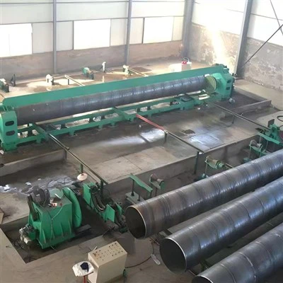
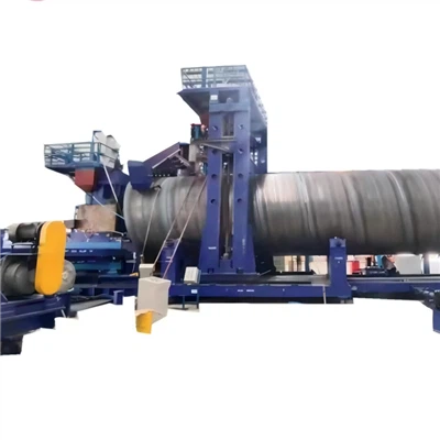
A spiral welding pipe machine, or SSAW pipe mill, is specialized industrial equipment for producing spiral seam welded pipes from steel strips via continuous spiral forming and submerged arc welding. Its key advantage is flexibility: it can make different-diameter pipes with the same-width steel strips and vice versa, making it ideal for large-scale production of large-diameter, thick-walled pipes. With high welding efficiency, uniform weld stress distribution, and broad adaptability to various steel materials, it serves as the core equipment in petroleum, natural gas, municipal engineering, and energy transmission sectors.
This guide covers basic cognition, structural composition, standard operation processes, core technical parameters, daily maintenance, common fault troubleshooting, and safety specifications. It balances professional accuracy with practical usability, providing valuable guidance for equipment operators, maintenance staff, and production managers to improve work efficiency, ensure product quality, and extend the service life of the equipment.
Basic Cognition and Classification
Core Definition
Spiral welding pipe machines process hot-rolled or cold-rolled steel strips into spiral seam pipes through a series of sequential and continuous operations: uncoiling, leveling, shearing, spiral forming, welding, sizing, and cutting. The main welding technologies adopted are submerged arc welding (SAW) and high-frequency welding (HFW), among which SAW is the most widely used due to its ability to produce high-quality, dense welds. The welding process melts the edges of the steel strip, forming a continuous spiral weld that effectively disperses stress, making the pipes suitable for high-pressure and large-diameter transmission applications.
Equipment Classification
Spiral welding pipe machines are classified into three main types based on their structural design and application scenarios, with key differences summarized in the following table:
|
Classification Type |
Structural Features |
Application Scenarios |
Core Advantages |
|
Front-swing Type |
Fixed forming machine, swinging welding torch, compact structure |
Medium-diameter (Φ508-1420mm) oil/gas pipes |
Flexible operation, easy specification adjustment, suitable for X70 steel grade |
|
Rear-swing Type |
Fixed welding torch, swinging forming machine, high stability |
Large-diameter (Φ406-2540mm) high-pressure pipes |
High welding precision, suitable for X80 steel grade (max 25.4mm wall thickness) |
|
Flying Welding Car-type |
Mobile welding car, capable of on-line tracking welding |
Medium/large-diameter (Φ377-2200mm) municipal pipes |
High production efficiency, 24-hour continuous operation, quick specification switching |
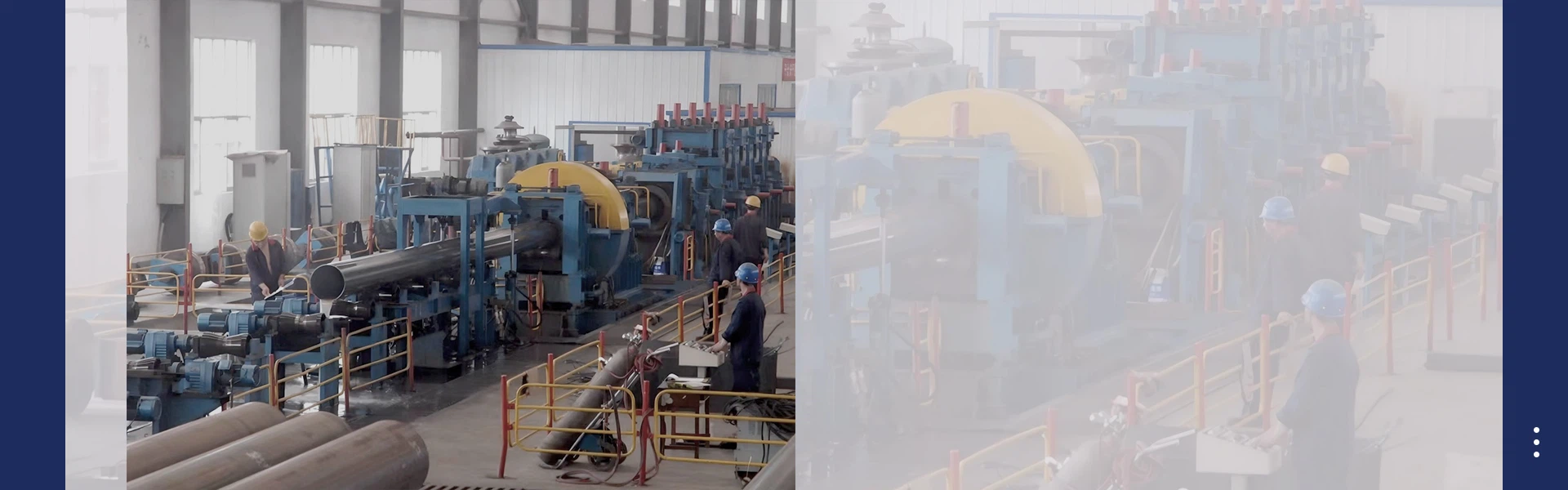
Structural Composition
Spiral welding pipe machines adopt a modular integrated design, which simplifies maintenance and allows flexible configuration according to production needs. The entire machine consists of 8 core functional units, among which the spiral forming unit and welding unit are the most critical, directly determining the quality of finished pipes and overall production efficiency.
1. Feeding and Pre-processing Unit
As the first stage of the pipe-making process, this unit is responsible for preparing steel strip raw materials for subsequent forming and welding. It includes key components such as an uncoiler, leveler, shearing and butt welding station, and edge trimmer. The uncoiler holds the steel coil and feeds the steel strip into the machine at a stable speed, equipped with a tension control device to prevent slipping or deviation. The leveler uses multiple sets of rollers to correct warpage or wave deformation, ensuring a flat surface and uniform thickness. The shearing and butt welding station trims the strip ends and welds consecutive steel coils seamlessly to achieve continuous production. The edge trimmer removes burrs and adjusts the edge angle, creating a clean, uniform edge for high-quality welding.
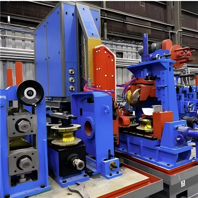
2. Spiral Forming Unit (Core)
Based on the three-roll plate bending principle, this unit shapes the leveled steel strip into a spiral pipe blank. It consists of forming rollers, guiding devices, and pre-bending devices. The steel strip is fed into the forming machine through the guiding device and gradually bent into a spiral shape at a preset angle (30°-60°). The edges of the strip are precisely aligned to form a V-shaped groove (60°-75°), which is crucial for ensuring full weld penetration. The adjustment accuracy of the forming machine directly affects the roundness of the pipe blank, the consistency of the spiral angle, and the quality of the subsequent weld.

3. Welding Unit (Core)
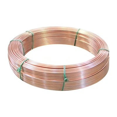
This unit is responsible for joining the edges of the spiral pipe blank to form a continuous, strong weld. It is equipped with double internal and external welding torches, a welding power supply, a wire feeding mechanism, and a flux recovery device. SAW is the mainstream welding technology, offering excellent weld quality and high efficiency. The internal torch is installed inside the pipe blank, while the external torch is fixed outside, enabling simultaneous double-sided welding. The wire feeding mechanism delivers welding wire to the weld zone stably, and the flux creates a protective atmosphere to reduce oxidation and improve weld quality. The flux recovery device collects and reuses unused flux, reducing production costs. The welding power supply adjusts current (200-500A) and voltage to match the steel strip material and thickness.
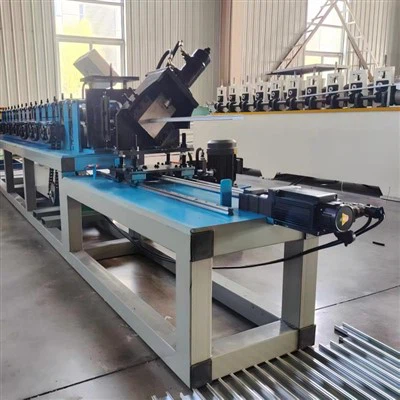
4. Key Auxiliary Units
Auxiliary units support the core functions to ensure smooth operation and high-quality output. The sizing and straightening unit uses multiple sizing rollers to calibrate the outer diameter and roundness, ensuring a dimensional tolerance of ±0.2mm, and corrects bending or spiral deformation to meet a straightness requirement of ≤1mm per meter. The cutting and finishing unit includes a flying saw and a chamfering machine: the flying saw tracks the pipe's movement online, cutting it to a fixed length with ±5mm accuracy and a maximum speed of 80m/min; the chamfering machine trims the pipe ends to remove burrs and ensure perpendicularity for easy connection. The PLC-based control system with a touch screen enables automatic operation, parameter setting, real-time monitoring, and fault alarm. The hydraulic and lubrication units provide stable power and reduce component wear, extending equipment service life.
Standard Operation Process
Following the standard operation process is essential for safe and efficient production, as well as ensuring product quality. The process is divided into three main stages:
1. Pre-startup Preparation
Operators must wear appropriate labor protection equipment (safety helmet, protective goggles, gloves, safety shoes) to prevent injury. They should thoroughly inspect the equipment: check that all connecting bolts are tight, forming rollers and welding torches are in good condition without wear or looseness, hydraulic and lubrication systems have sufficient oil levels, and the electrical system and safety devices (e.g., emergency stop buttons) are functioning properly. Raw materials must be prepared: ensure the steel strip's material and specifications (thickness, width) meet production requirements, and the strip is free of rust, oil stains, or other defects. Finally, set core parameters via the touch screen, including forming angle, welding current (200-500A), production speed (10-60m/min), and cutting length, in accordance with the equipment manual.
2. Startup and Operation
Start the machine in the specified order to avoid component damage: main power supply → hydraulic system → lubrication system → cooling water system → feeding unit → forming unit → welding unit → cutting unit. After starting each unit, observe its operation for abnormalities before proceeding to the next. Conduct a trial production of 3-5 short pipes to check the forming quality, weld uniformity, and dimensional accuracy. Adjust parameters such as forming angle or welding current if issues are found, until the products meet the required standards. During normal production, operators must monitor the machine continuously to ensure stable steel strip feeding, uniform welding, and precise cutting.
3. Shutdown and Cleaning
Shut down the machine in the reverse order of startup to protect its components. After shutdown, clean the welding unit to remove weld slag and unused flux, clean forming rollers and cutting tools to eliminate debris, and wipe the entire machine to keep it clean. Record key operation details, including running time, production quantity, parameter settings, and any issues encountered, to ensure a smooth handover to the next shift.
Core Technical Parameters
The performance of spiral welding pipe machines is determined by core technical parameters, which vary by model. The following table provides an overview of key parameters for three mainstream models, serving as a reference for equipment selection and parameter setting:
|
Model |
Pipe Outer Diameter |
Steel Strip Thickness |
Welding Current |
Production Speed |
Steel Grade |
|
SSAW-500 (Small) |
Φ160-500mm |
2-8mm |
200-350A |
10-30m/min |
Q235, Q355 |
|
SSAW-1420 (Medium) |
Φ508-1420mm |
6-20mm |
300-450A |
15-45m/min |
X70 |
|
SSAW-2540 (Large) |
Φ406-2540mm |
6-25.4mm |
400-500A |
20-60m/min |
X80 |
Daily Maintenance
Regular maintenance is crucial to extending equipment service life, reducing fault frequency, and ensuring stable production. It follows the principle of "regular inspection, timely maintenance, and replacement as needed" and is divided into four cycles:
Daily Maintenance
Conducted before startup and after shutdown. Check oil levels of hydraulic and lubrication systems, supplement oil if necessary. Clean debris and weld slag from the welding unit and forming rollers, tighten loose bolts, and ensure the cooling water system functions properly with a water temperature of 25-40℃.
Weekly Maintenance
Inspect forming rollers and welding torches for wear, adjust the wire feeding mechanism to ensure stable wire delivery, clean hydraulic system filters to remove impurities, check the tightness of chains and belts, and lubricate all rotating components (e.g., bearings)
Monthly Maintenance
Calibrate welding current and voltage to ensure accuracy, check the cutting precision of the flying saw and replace worn saw blades if needed, inspect the hydraulic system for leaks and replace aging seals, and conduct a comprehensive check of electrical lines to prevent safety hazards.
Annual Maintenance
Fully disassemble and clean the machine, replace severely worn components (e.g., forming rollers, bearings), change hydraulic and lubricating oil, perform derusting and anti-corrosion treatment on the machine frame, and invite the equipment manufacturer to conduct a comprehensive inspection to identify potential faults.
Common Fault Troubleshooting
During production, spiral welding pipe machines may experience faults that affect production progress and product quality. The following table lists common faults and corresponding practical solutions for quick resolution:
|
Fault Phenomenon |
Solutions |
|
Weld air holes/incomplete welding |
Replace unqualified flux, adjust the welding torch position for precise alignment, calibrate welding current and voltage, and clean oil stains or rust from steel strip edges. |
|
Irregular pipe forming |
Recalibrate the forming angle, replace worn forming rollers, adjust the uncoiler tension to ensure uniform feeding, and use steel strips of consistent thickness. |
|
Flying saw length deviation |
Reset the cutting length parameters, calibrate the flying saw's tracking speed to match the pipe's movement, and replace worn saw blades. |
|
Abnormal noise/vibration |
Tighten loose connecting bolts, replace worn bearings or forming rollers, adjust the hydraulic system pressure to ensure stability, and adjust the tightness of chains and belts. |
Safety Specifications
Spiral welding pipe machines are large-scale mechanical equipment involving electrical, hydraulic, and high-temperature welding processes, so safety is a top priority. Operators must strictly adhere to the following specifications to prevent accidents:
Operators must receive professional training, pass assessments, and obtain an operation qualification certificate before taking up the job. They must wear appropriate labor protection equipment at all times during operation. Fire-fighting equipment should be readily available in the welding area, and smoking or storing flammable materials is strictly prohibited. During operation, operators must not touch moving components (e.g., forming rollers, welding torches) or open the equipment's protective cover. When adjusting parameters, cleaning, or troubleshooting, the machine must be shut down and the main power supply cut off, with a "No Closing, Under Maintenance" sign displayed. Any abnormalities during operation must trigger an immediate shutdown to avoid equipment damage or personal injury. Overloading the machine is prohibited, and the production site must be kept clean and unobstructed. Regular safety training and emergency drills should be conducted to improve operators' safety awareness and emergency response capabilities.
Conclusion
The spiral welding pipe machine is critical equipment for producing large-diameter, thick-walled steel pipes, with its performance directly affecting production efficiency, product quality, and equipment service life. This guide comprehensively covers all essential aspects of the equipment, from basic cognition to safety operation. As the manufacturing industry moves toward intelligence and green production, spiral welding pipe machines will continue to integrate advanced technologies, becoming more efficient and user-friendly. By following the guidelines in this document, operators and maintenance personnel can ensure the machine operates safely and efficiently, maximizing its value and supporting the high-quality development of key industries such as petroleum, natural gas, and municipal engineering.