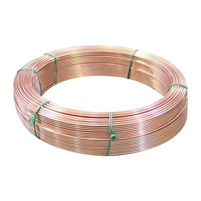
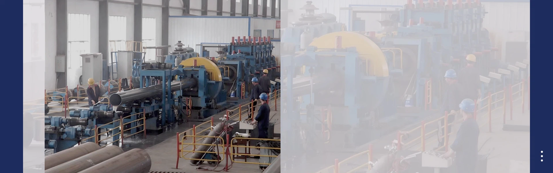
A slitting machine, also known as a coil slitting production line, is a continuous rotary shearing device used to longitudinally cut wide metal parent coils into multiple narrow strip coils without altering the material thickness. Unlike transverse cutting machines that produce flat sheets by cutting coils to fixed lengths, slitting machines perform longitudinal cuts along the rolling direction of incoming strip steel, producing compact narrow coils for downstream industries such as ERW pipe mills, roll forming machines, stamping shops, and steel service centers.

Many operators mistakenly believe that slitting is merely a simple cutting process. In fact, high-quality slitting relies on the coordinated operation of subsystems such as unwinding, straightening, guiding, shearing, tension control, and rewinding. The blade gap, material centering, and stable material tension directly determine the quality of the finished product. If the equipment is not adjusted properly, it will result in problems such as burrs, material deviation, surface scratches, and shrinkage of the roll, thereby causing potential defects in subsequent roll forming or high-frequency welding processes.
Core cutting principle: rotary shear slitting
The main working principle of the industrial metal cutting band machine is rotational shearing and cutting. Its operation mode is similar to a pair of continuously rotating large scissors. On two parallel heavy upper and lower armatures, there are multiple circular blade steel plates and precise spacer washers. These washers can precisely control the width of each finished narrow band.
When the steel strip passes between the rotating upper and lower circular knives in the opposite direction, the controlled vertical overlap and small horizontal gap generate shear force. The material separates along the cutting line through plastic fracture rather than melting. The horizontal gap is the most important setting parameter, usually set at 6% to 10% of the thickness of the carbon steel workpiece. If the gap is too large, the material will tear and produce a large amount of burrs; if the gap is too small, it will cause tool friction, rapid wear, and secondary micro-burrs.
Apart from rotary shear cutting, razor-type cutting is suitable for processing ultra-thin foils and soft materials. However, due to its poor wear resistance against thick or hard metals, razor-type cutting is rarely used in the production of general-purpose steel coils. Almost all cutting lines used for pipe manufacturing and raw material preparation for profiles employ rotary shear cutting technology.
It must be noted that slitting only changes strip width. Material thickness, chemical composition and original‑coil surface defects remain unchanged after processing. Slitting cannot eliminate scratches, rust or laminations inherited from incoming master coils.
Main sections of a complete slitting line
A full‑function slitting‑line can be divided into entry section, slitter‑head section and exit (recoiling) section, each undertaking sequential tasks.
2.1 Entry section: unwinding, levelling and web guiding
The workflow starts in the entry zone. A hydraulic coil‑car transports heavy master coils and loads them onto the expandable uncoiler mandrel. The expanding mandrel grips the coil inner diameter firmly. Controlled braking torque maintains stable unwinding tension to avoid slack or over‑speed pay‑off during production.
After unwinding, the strip goes through pinch rolls and multi‑roll levelers. The leveler removes "coil‑set", the natural curvature memory formed during prior coil rolling, delivering flat strip into the slitter head. Without levelling, curved material will generate unstable cutting and poor‑quality finished coils.
An Edge‑Position‑Control (EPC) guiding system uses ultrasonic or optical sensors to track strip edge position in real‑time. Hydraulic actuators adjust the uncoiler or steering roller laterally, preventing strip wandering before entering the knives. Accurate guiding guarantees consistent finished‑width tolerance. Some lines equip looping pits as material buffer zones. The loop pit permits continuous slitting while operators weld coil ends together during coil change‑over, avoiding frequent full‑line stops.
2.2 Slitter‑head section: the heart of slitting operation
The slitter‑head is where actual cutting takes place. Rigid high‑precision upper and lower arbors hold circular knives, spacing washers and shims. Before production starts, operators assemble knives and spacers according to order‑required strip widths. Arbor rigidity is critical; arbor deflection under cutting load will cause unstable knife clearance and inconsistent edge quality across strip width.
As flat, correctly‑aligned strip feeds into rotating knife sets, simultaneous longitudinal shearing divides one wide web into several independent narrow strips. Trim‑edge scrap generated from coil two sides is guided toward scrap winders or scrap choppers. Trim scrap can be collected and recycled as metallurgical raw material, improving overall material yield rate.
After cutting, strip separators physically keep newly‑slit narrow strips apart. Without separators, adjacent moving strips will rub against each other and produce irreversible surface scratches, which are especially harmful for polished stainless‑steel feedstock for swimming‑pool equipment production.
2.3 Exit section: tension station and recoiling
Even after clean shearing, slitted strips cannot directly enter the recoiler. A tension station creates uniform, consistent pulling force across all narrow strips simultaneously. This is one of the most frequently‑understood parts of slitting‑machine operation. Different narrow strips would run at inconsistent speed and produce wrinkled, loose or telescoped finished coils without a dedicated tension‑generating unit.
Tension is generated by friction between strips and special tension‑roll groups. Every narrow strip obtains identical web tension regardless of width difference. Under stable tension, separated strips travel to the recoiler expandable mandrel. Separator discs fitted on the recoiler mandrel prevent different narrow coils from interleaving during winding.
The recoiler rewinds individual strips into tight, well‑shaped finished slit coils. Modern lines adopt taper‑tension control: winding tension gradually reduces as coil outer‑diameter increases, preventing inner‑layer coil crushing and deformation. When the whole master‑coil processing finishes, the line stops. An unloading car removes finished slit coils for strapping, marking and delivery.
Step‑by‑step complete operating workflow
First comes preparation and tooling setup. Operators confirm order specifications including material grade, thickness and target slit widths. Technicians assemble knives, spacers and shims on slitter arbors, adjust knife horizontal clearance and vertical overlap matched to material thickness and hardness. Knife sharpness is inspected; worn blades require re‑grinding before use.
Second, coil loading and threading. A coil car lifts the master coil onto the uncoiler mandrel. Operators expand the mandrel to lock the coil. The strip leading‑edge is manually or mechanically threaded through pinch rolls, leveler, EPC guiding unit, slitter‑head, separators, tension station and finally onto the recoiler mandrel.
Third, low‑speed trial run. The machine runs at reduced speed for short distance. Operators inspect actual slit‑strip width, edge burr height and surface condition. Fine‑tuning for knife clearance, guiding position and tension parameters is performed until all indexes meet specification requirements. Trial‑run scrap material is discarded.
Fourth, formal continuous production. The line ramps up to normal working speed. Operators continuously monitor edge quality, tension status and strip surface. Minor adjustments are made during production if burrs or wandering appear. Trim scrap is collected by scrap‑processing devices.
Fifth, completion and unloading. When the entire master coil is completely slit, equipment decelerates and stops. Finished slit coils are strapped, labelled and unloaded. Knives and spacers can be disassembled for next‑order reconfiguration.
Key critical adjustment parameters
Knife horizontal clearance is the dominant parameter, normally 6‑10 % of material thickness for carbon steel. Harder stainless‑steel material requires corresponding clearance adjustment. Vertical overlap defines how deeply upper and lower knives interlock. Insufficient overlap results in incomplete separation; excessive overlap accelerates tool wear.
Web tension includes unwinding tension, intermediate tension and recoiling taper tension. Too‑high tension stretches thin‑gauge material and causes permanent strip elongation; insufficient tension creates wrinkling and loose coils. EPC guiding sensitivity must match line running speed to eliminate strip wandering. Knife sharpness and arbor run‑out also heavily influence long‑term cutting stability.
Typical defects caused by incorrect slitting‑machine operation
Excessive burr is the most‑common defect, mainly originating from improper knife clearance or dull cutting edges. Burrs will scratch forming rolls in downstream roll‑forming lines and generate welding defects for ERW tube‑making. Strip wandering and inconsistent width stem from EPC guiding failure or arbor deflection. Surface scratches happen when separators or guide rollers are damaged or improperly adjusted. Telescoped coils appear when recoiling tension is unstable. All these defects will pass to downstream manufacturing processes and cause economic losses.
Application value and process limitations
Slitting machines deliver custom‑width narrow coils from standard‑size mill master coils, solving dimension mismatch between steel‑mill output and diverse downstream requirements. High‑quality slit strips are essential raw‑material for ERW tube mills, purlin roll‑forming lines and stamping plants. Nevertheless, slitting cannot correct incoming‑coil thickness or surface flaws. Operator experience and regular knife re‑grinding are compulsory for stable output.
In summary, a slitting machine processes wide master coils into multiple narrow finished coils through rotary‑shear longitudinal cutting. Its complete workflow consists of coil loading, unwinding, levelling, edge‑guiding, rotary‑knife shearing, scrap removal, strip separation, tension‑control recoiling and finished‑coil unloading.
Rotary shear cutting relies on precisely‑adjusted knife horizontal clearance and vertical overlap to achieve clean metal separation. The whole line depends on coordinated performance of entry, slitter‑head and exit sections. Stable web‑tension control and accurate edge‑position guiding are equally important as cutting‑knife setup. Improper parameter adjustment will produce burrs, wandering strips, surface scratches and defective rewound coils, creating risks for subsequent tube‑making and roll‑forming production.
Understanding how a slitting machine works helps production and procurement staff evaluate slit‑strip quality, judge equipment performance and communicate clearly with steel‑service‑centre suppliers. As modern metal manufacturing demands tighter dimensional tolerances, slitting‑line technology keeps advancing toward automatic knife‑setting, intelligent closed‑loop tension control and higher processing speed to satisfy growing market requirements for custom‑size metal strip products.