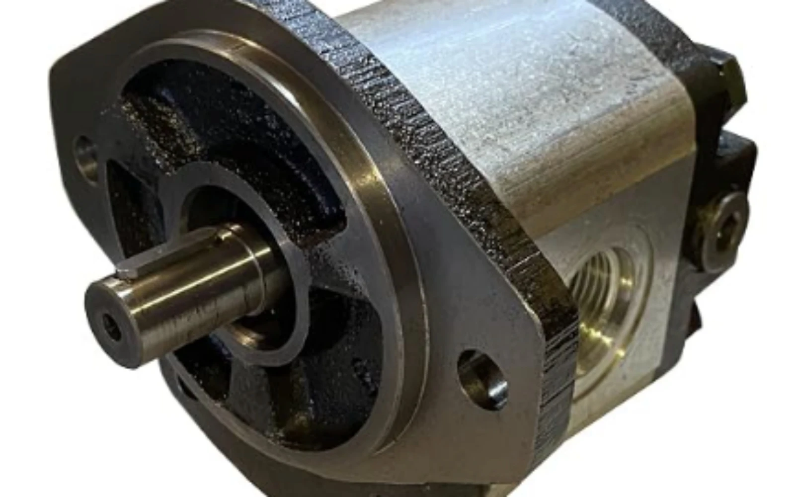
A hydraulic gear pump is one of the most widely-used positive-displacement pumps in fluid power systems. As a core power-conversion component, it transforms mechanical rotational energy from electric motors or internal-combustion engines into hydraulic fluid pressure energy. By meshing a pair of precisely-manufactured gears inside a tight-fitted housing, it traps and transports fixed volumes of hydraulic oil with each rotation.
Compared with other hydraulic pump categories such as piston pumps and vane pumps, gear pumps stand out for their simple mechanical layout, low manufacturing cost, compact size, robust construction and reliable operation under harsh working environments. They are extensively deployed in machine tools, construction machinery, agricultural equipment, roll-forming production lines, tube-making machinery, material-handling systems and general industrial hydraulic stations. Although gear-pump technology is mature, it has inherent performance boundaries regarding pressure capability, volumetric efficiency and noise output.
Basic working principle of hydraulic gear pump
The hydraulic gear pump belongs to the positive-displacement pump family. Positive-displacement pumps deliver a nearly constant volume of fluid per shaft revolution, unlike centrifugal pumps whose output flow changes heavily with system back-pressure.
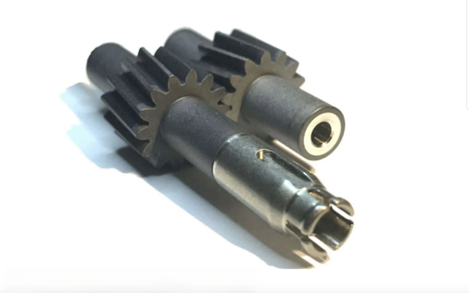
Inside the pump housing sit two close-fitting spur or helical gears: a driving gear connected to the input drive shaft, and a driven gear that rotates passively by meshing with the driving gear. Small, precise clearances exist between gear tooth tips and housing bore, as well as between gear end faces and side-plate / bearing assemblies.
When the driving gear rotates, gear teeth disengage on the inlet (suction) side of the pump chamber. Disengagement enlarges local cavity volume and creates partial vacuum. Atmospheric pressure pushes hydraulic oil from the reservoir through suction piping into the spaces between gear teeth. Oil becomes physically trapped within the tooth gaps between gear teeth and the inner pump housing. As gears keep turning, these trapped oil volumes travel along the inner circumference of the housing toward the discharge (pressure) side.
At the discharge side, gear teeth begin to mesh tightly with one another. Meshing action reduces the volume between adjacent teeth and squeezes trapped oil out into the pressure outlet port, generating system hydraulic pressure. Meshing gear teeth prevent high-pressure oil from flowing backward directly from outlet back to suction port.
It is critical to note that gear pumps do not generate pressure by themselves. They produce continuous fluid flow. System working pressure builds up only when hydraulic fluid meets resistance from cylinders, motors, valves and pipe-network loads. System pressure is determined by external load, not by the pump's internal geometry.
A small quantity of high-pressure oil leaks internally across the tiny clearances between gears, side plates and housing. This internal leakage, also known as slip, reduces volumetric efficiency and is an unavoidable feature of gear-pump construction.
Two major structural types: external gear pump and internal gear pump
Hydraulic gear pumps fall into two primary groups: external gear pumps and internal gear pumps. External gear pumps dominate general-purpose industrial applications, while internal gear pumps serve specialized working scenarios.
2.1 External gear pump
The external gear pump is the most common variant. Two identical external-tooth gears mesh together side-by-side within the pump housing. Shaft bearings support both gear shafts. Many modern industrial external gear pumps adopt floating side-plate design. High-pressure discharge oil acts on the rear surface of side plates, pushing plates tightly against gear end faces. This design automatically compensates for wear-induced end-face clearance and improves volumetric efficiency under elevated pressure.
External gear pumps are compact, inexpensive and easy to assemble. Most medium-pressure hydraulic stations on metal-processing machinery such as slitting lines, ERW tube mills and roll-forming equipment use external gear pumps. Their typical working-pressure range covers 7 MPa up to 25 MPa. High-pressure heavy-duty versions can reach approximately 30 MPa.
Limitations of external gear pumps include relatively higher operating noise level and obvious flow pulsation caused by periodic gear-tooth meshing. Output flow fluctuates slightly for every gear rotation. Furthermore, external gear pumps are sensitive to oil contamination; solid particles in hydraulic oil accelerate wear on gear surfaces, side plates and bearings.
2.2 Internal gear pump
An internal gear pump consists of an outer internal-toothed ring gear and a smaller external-toothed pinion gear meshing inside the ring gear. A crescent-shaped partition component separates suction zone from pressure zone. As the pinion drives the ring gear to rotate, volume variation between gear teeth completes oil suction and oil discharge cycles.
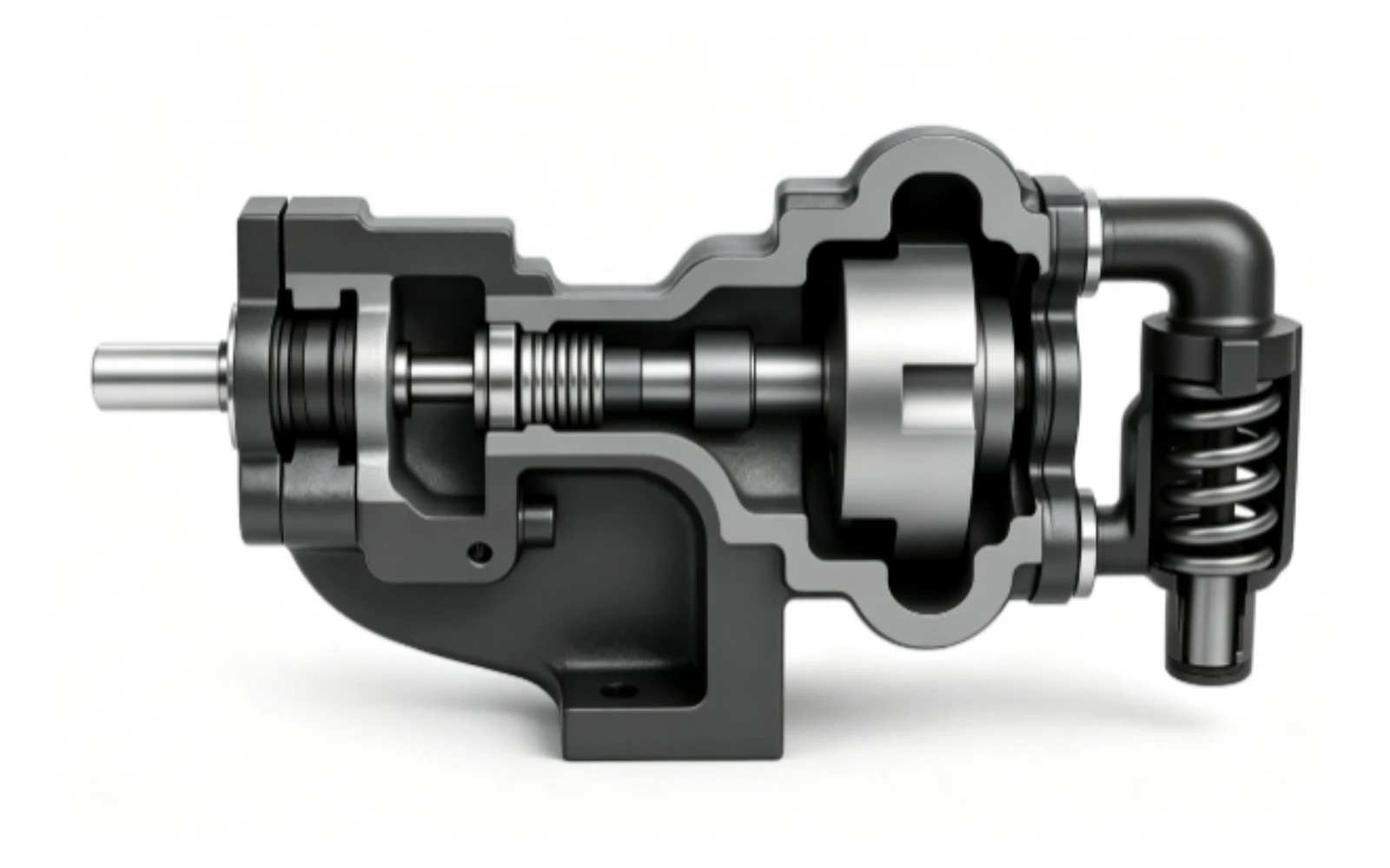
Internal gear pumps deliver smoother fluid flow with lower pulsation and quieter running noise. They perform well for high-viscosity-fluid transfer. However, internal-gear-pump manufacturing complexity and cost are higher. For general-purpose high-flow hydraulic power transmission, external gear pumps remain the preferred economic choice. Internal gear pumps find more applications in lubrication circuits, oil-transfer stations and special-viscosity-medium processing rather than main high-power actuation circuits.
Key performance-evaluation parameters
Several core technical parameters define gear-pump performance for engineering selection.
Displacement describes the theoretical oil volume delivered per single shaft revolution, measured in cubic centimetres per revolution (cc/rev). Output theoretical flow equals displacement multiplied by rotational speed. Due to internal slip, actual delivered flow is always lower than theoretical calculation.
Volumetric efficiency equals actual output flow divided by theoretical flow. Wear-free new external gear pumps commonly achieve volumetric efficiency of 85 %-92 %. As internal components wear over service time, clearances enlarge, slip increases and volumetric efficiency gradually drops. Sharp decline in volumetric efficiency represents a typical fault signal indicating pump wear requiring overhaul or replacement.
Overall efficiency takes both volumetric loss and mechanical friction loss into consideration. Mechanical friction originates from gear meshing and bearing rotation. Operating-pressure rating defines the maximum continuous working pressure the pump can sustain. Running continuously above rated pressure will drastically shorten service life and cause seal failure.
Rotational-speed range is another important restriction. Operating below minimum speed worsens suction performance and may trigger cavitation. Excessive high speed amplifies noise, wear and cavitation risk. Viscosity of hydraulic oil must match pump specification; overly-thin oil increases internal slip, while excessively-thick oil creates suction difficulties.
Main advantages of hydraulic gear pumps
First of all, simple and compact mechanical construction brings significant cost benefits. Compared with axial-piston pumps containing complex swash-plate, piston-shoe and valve-plate assemblies, gear pumps have far fewer precision-moving parts. Purchase price and spare-part cost stay relatively low.
Secondly, gear pumps possess strong mechanical robustness. They tolerate moderate shock-load conditions and are less vulnerable to pressure spikes than vane pumps. This makes them suitable for mobile machinery and industrial production-line hydraulic systems.
Thirdly, easy installation and maintenance. Most external gear-pump designs allow straightforward shaft coupling with electric motors. Many models feature modular construction; different displacement pumps can share identical mounting flange and shaft dimensions for convenient interchange on hydraulic stations.
Fourth, adaptability to diverse fluid media. Besides standard hydraulic mineral oil, properly-selected gear pumps can transfer certain synthetic fluids, lubricating oils and even some high-viscosity liquids.
These merits explain why gear pumps are widely fitted onto auxiliary hydraulic circuits of roll-forming machines, tube-mill hydraulic systems, material-clamping mechanisms and cooling-oil supply loops.
Disadvantages and application limits
Hydraulic gear pumps also show clear technical limitations.
The most obvious shortcoming is internal leakage. Even well-conditioned gear pumps have measurable slip. When working pressure rises, internal slip increases accordingly. For ultra-high-pressure hydraulic systems above 30 MPa, piston pumps normally replace gear-pump solutions.
Output flow cannot be adjusted without additional external components. Standard gear pumps are fixed-displacement pumps. Their flow output changes only with drive-shaft rotational speed. They cannot realize variable-displacement function like variable-piston pumps. To regulate flow, system designers must install proportional valves or use variable-speed motor drives, which adds extra system cost.
Gear pumps generate noticeable flow pulsation and mechanical noise originating from gear-tooth meshing. Noise becomes more prominent at high rotational speed and high working pressure. Therefore, gear pumps are less ideal for noise-sensitive indoor precision-equipment environments.
Another critical weakness is poor anti-contamination performance. Tiny solid impurities inside hydraulic oil scratch gear tooth surfaces and side-plate contact surfaces. Progressive wear enlarges internal clearances, volumetric efficiency drops, and system performance degrades. Effective oil filtration is compulsory for extending gear-pump service life. In addition, gear pumps are susceptible to cavitation: insufficient suction-pipe diameter, clogged suction filters or excessively high oil viscosity will produce cavitation, accompanied by sharp noise and accelerated component erosion.
Common typical faults
Frequent real-world gear-pump failures include insufficient output flow and low system pressure, mostly caused by side-plate and gear-tooth wear and increased internal slip. Abnormal loud noise can result from cavitation, bearing damage, gear-tooth surface scoring or misalignment between motor shaft and pump shaft. External oil leakage usually arises from failed shaft seals, loose housing fasteners or damaged gaskets.
Operators should avoid running gear pumps under long-term over-pressure conditions. Over-pressure accelerates wear and may cause permanent mechanical damage. Routine maintenance tasks include monitoring hydraulic-oil cleanliness, replacing filter cartridges on schedule and checking noise and pressure-readout changes as early fault warning indicators.
Practical application scenarios
External fixed-displacement gear pumps dominate medium-pressure general-purpose hydraulic power units. They serve clamping devices, feeding mechanisms, lifting circuits and auxiliary actuation loops. On metal-processing production lines such as slitting machines and ERW tube mills, gear pumps often supply hydraulic power for coil-car movement, uncoiler expansion, hold-down rollers and shear-device actuation.
For high-pressure main drive loops or energy-saving variable-flow-demand systems, engineers prefer variable-displacement piston pumps. Internal gear pumps are selected for low-pressure lubrication circuits and high-viscosity-fluid transfer. Gear pumps are rarely adopted for ultra-precision low-noise servo hydraulic systems.
In conclusion, a hydraulic gear pump is a fixed-displacement positive-displacement hydraulic component that converts rotating mechanical power into hydraulic-oil flow energy. External gear pumps, constructed with two meshing external gears, represent the most-popular type, while internal gear pumps are used for special-purpose conditions.
Its working principle relies on volume change generated by gear-tooth disengagement and meshing: creating partial vacuum for oil suction on one side and squeezing out pressurized fluid on the discharge side. Key performance indicators include displacement, volumetric efficiency, rated pressure and rotational-speed range. Gear pumps benefit from compact size, simple structure, low cost and robust mechanical performance, making them ubiquitous across industrial hydraulic stations, construction machinery and metal-processing equipment.
Nevertheless, gear pumps have inherent constraints: fixed displacement, internal slip that rises under high pressure, flow pulsation, noise output and sensitivity to oil contamination. They cannot compete with piston pumps for ultra-high-pressure and variable-flow requirements. Understanding operating principles, advantages and failure modes of hydraulic gear pumps supports mechanical technicians in proper pump-type selection, system design and daily maintenance, ensuring stable operation of hydraulic systems for manufacturing-production-line machinery.