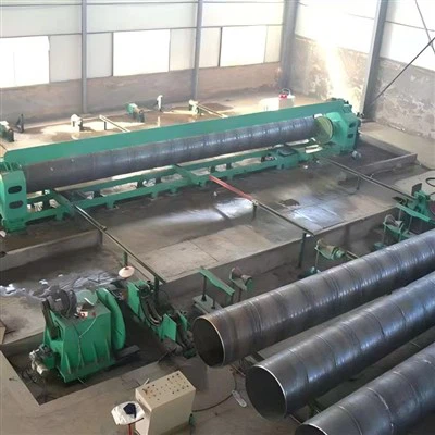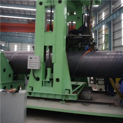
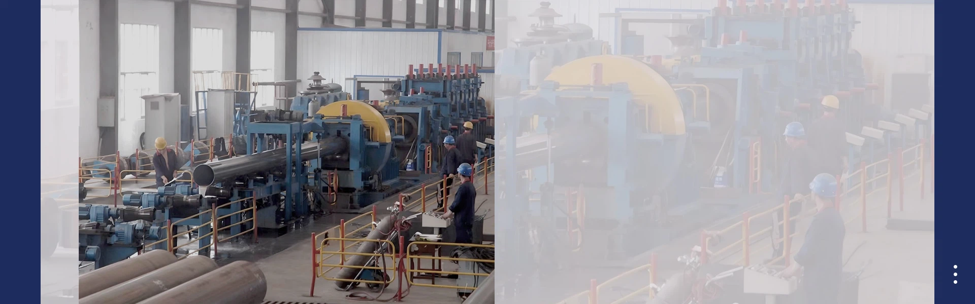
Spiral welding, usually carried out in the form of spiral submerged arc welding (SSAW), is an efficient and continuous metal connection and pipe forming technology. It is the core manufacturing process for large-diameter spiral welded steel pipes. This technology integrates cold rolling forming and double-sided submerged arc welding into a continuous and uninterrupted production line: flat steel coils are fed in at an inclined spiral angle, gradually forming a cylindrical pipe body, and continuous welding is simultaneously performed at the spiral joints. Unlike the straight welds parallel to the pipe axis formed by longitudinal welding processes, spiral welding produces continuous spiral welds around the pipe body, giving the final product unique structure and economic characteristics.
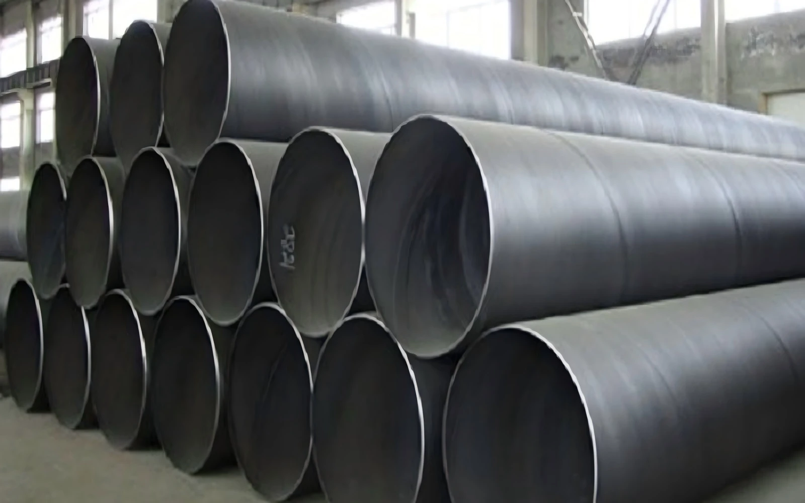
After decades of technological development, spiral welding has evolved into a mature, standardized and widely applied manufacturing process. It dominates the production of medium-pressure large-diameter steel pipes and plays an irreplaceable role in the transportation of oil and gas, municipal water supply and drainage, foundation piers and dredging projects.
Definition and Fundamental Working Principle
1.1 Basic Definition of Spiral Welding
Spiral welding is a continuous arc welding process used to manufacture steel pipes by forming hot-rolled steel strip into a helically wound cylindrical shape and fusion-welding the abutting edges along the resulting spiral seam. In industrial production, the process is almost universally paired with submerged arc welding (SAW) technology, so the term "spiral welding" in the pipeline industry is generally equivalent to spiral submerged arc welding.
The most distinctive feature that distinguishes spiral welding from other pipe welding methods is the orientation of the weld. In ERW and LSAW processes, the weld runs straight along the length of the pipe parallel to the pipe axis. In spiral welding, the weld forms a continuous helix around the pipe, typically at an angle of 30° to 70° relative to the pipe axis. This helical geometry is not simply a manufacturing by-product - it is an intentional design that influences stress distribution, production flexibility and structural rigidity.
1.2 Core Forming and Welding Mechanism
The working principle of spiral welding is based on two interlinked processes: helical forming and submerged arc fusion. First, the flat steel strip is fed into the forming station at a precise inclined angle known as the forming angle. As the strip advances, a set of forming rollers bends it progressively into a cylindrical tube blank, with the two strip edges meeting continuously along a helical line.
The gap between the two abutting edges is precisely controlled. Internal and external welding torches are positioned at the seam to perform double-sided submerged arc welding. The forming angle is the key process parameter: for a given strip width, increasing the forming angle produces a smaller pipe diameter, while decreasing the angle produces a larger diameter. This relationship is the source of spiral welding's famous production flexibility - the same raw material can yield multiple pipe diameters simply by adjusting the forming angle.
From a structural mechanics perspective, the inclined weld distributes stress more evenly. Under internal pressure, a pipe experiences maximum hoop stress in the circumferential direction and lower axial stress. In a longitudinal welded pipe, the weld is aligned with the direction of maximum hoop stress. In a spiral welded pipe, the weld sits at an angle to both principal stresses, so no single weld section bears the full peak hoop stress. This distributed stress state improves crack propagation resistance and overall structural safety.
Raw Materials and Core Equipment
2.1 Raw Material Requirements
Spiral welding uses hot-rolled steel coil as the base material, covering carbon steel grades such as Q235B and Q355B as well as micro-alloyed pipeline steels including X52, X60 and X70, in accordance with standards such as API 5L and GB/T 9711. The coil must have uniform thickness, good flatness and consistent mechanical properties to ensure stable forming and welding quality.
The welding consumables consist of solid welding wire and granular submerged arc flux. Common wire grades include H08A and H08MnA, selected to match the strength and toughness of the base metal. The flux performs multiple functions: it shields the arc and molten pool from atmospheric contamination, participates in metallurgical reactions to refine the weld microstructure, and forms a protective slag layer over the cooling weld. Proper flux handling and drying are essential to avoid porosity and hydrogen-induced cracking.
2.2 Key Equipment Units
A complete spiral welding production line consists of several sequentially arranged functional units.
Uncoiling and leveling unit: Loads and unwinds the heavy steel coil, then flattens the strip through multiple leveling rollers to eliminate coil set and residual stress.
Edge milling unit: Machines both edges of the strip to the required width and prepares a precise X or V bevel profile for full-penetration welding.
Spiral forming stand: The heart of the line, using multiple forming rollers to bend the strip into a continuous tube blank at the set forming angle.
Double-sided SAW welding system: Includes internal and external welding heads, usually configured as twin-wire or triple-wire systems for high deposition and deep penetration, plus automatic flux delivery and recovery.
Sizing and straightening unit: Corrects pipe ovality and straightness after welding, compensating for springback.
Flying cut-off system: Cuts the continuous pipe to fixed lengths without stopping the line, maintaining uninterrupted production.
Complete Spiral Welding Process Flow
3.1 Pre-Welding Preparation
The process begins with coil loading and uncoiling. The strip head is fed through a leveler to remove curvature and internal stress. The two edges of the strip are then milled to exact width and bevel geometry, ensuring consistent fit-up along the entire weld seam. To achieve fully continuous production, the tail of the previous coil is welded to the head of the next coil, eliminating downtime between coils.
3.2 Spiral Forming and Internal Welding
The prepared strip enters the spiral forming station, where forming rollers guide it into a helical curl and maintain a precise root gap at the abutting edges. The first welding operation is internal welding: the internal welding torch extends into the tube blank and strikes an arc buried under a layer of flux. Internal welding is responsible for full penetration of the weld root, which is critical for pressure-bearing performance. Modern lines use twin-wire internal welding to increase deposition rate and improve root fusion.
3.3 External Welding
As the rotating tube blank advances helically, the same spiral seam reaches the external welding station a short distance downstream. The external torch performs a second submerged arc weld from the outside of the pipe, filling the bevel completely and building up the required weld reinforcement. The combination of internal root pass and external fill pass ensures full through-thickness fusion and a sound, ductile weld joint. The molten slag solidifies over the hot weld, protecting it from oxidation and controlling cooling rate.
3.4 Post-Welding Sizing and Cut-to-Length
After welding, the pipe passes through sizing rollers that calibrate outer diameter, roundness and straightness. This step corrects minor elastic springback and ensures dimensional compliance with specification. Once the pipe reaches the preset finished length, a flying saw or plasma cutting device cuts it to size while the line continues running. This non-stop cutting is essential for maintaining the high productivity of spiral welding.
3.5 Finishing and Inspection Preparation
Cut pipes are conveyed to the finishing area where pipe ends are beveled for field welding and deburred. The pipes then move on to non-destructive testing and hydrostatic testing before final acceptance.
Core Technical Characteristics of Spiral Welding
4.1 Fully Continuous High-Efficiency Production
The most prominent feature of spiral welding is its fully continuous production mode. Unlike LSAW production, which requires intermittent loading and positioning of individual steel plates, spiral welding runs uninterrupted from coil to finished pipe. This continuity delivers very high output rates and shortens delivery lead times for large orders.
4.2 Unmatched Specification Flexibility
Because pipe diameter is controlled by the forming angle rather than raw material width, one production line can manufacture a wide range of diameters using the same coil width. Changeover between diameters requires only parameter adjustment, not major tooling replacement. This flexibility makes spiral welding highly responsive to mixed-specification orders and customized project requirements.
4.3 Optimized Weld Stress Distribution
As noted earlier, the helical weld orientation distributes hoop and axial stresses obliquely across the weld plane, reducing peak stress per unit weld length. This geometry also interrupts straight-line crack propagation, improving fatigue performance under cyclic pressure and bending loads. The continuous spiral weld also acts like a helical stiffener, enhancing the pipe's ring stiffness and resistance to ovalization under external soil pressure.
4.4 Stable and Repeatable Weld Quality
Because spiral welding uses fully mechanized submerged arc welding with consistent parameters, weld quality is highly uniform from pipe to pipe. The flux blanket provides excellent atmospheric shielding, resulting in low porosity, minimal oxide inclusions and a dense metallurgical structure. Weld joint efficiency typically reaches 90% or higher, meeting all major international pipeline standards.
Comparison with Other Pipe Welding Processes
5.1 Spiral Welding vs. Longitudinal Submerged Arc Welding (LSAW)
Spiral welding excels in continuous productivity, diameter flexibility and cost, and is best suited for medium-pressure large-diameter pipes. LSAW, which welds a single straight seam on pre-formed plate cylinders, can achieve heavier wall thicknesses and higher steel grades, making it preferred for high-pressure high-grade oil and gas trunk lines. However, LSAW is less flexible in diameter and generally more expensive per ton.
5.2 Spiral Welding vs. Electric Resistance Welding (ERW)
ERW uses high-frequency current to pressure-weld strip edges without filler metal, and is most economical for small and medium diameters with thinner walls. Spiral welding, by contrast, uses filler metal and full-penetration SAW, can produce much larger diameters and thicker walls, and delivers higher pressure-bearing capacity. The two processes serve largely complementary diameter and pressure ranges.